Step 1:
Turn the playstation upside down and
remove the 6 screws from the base.
Turn the playstation back over and remove the top cover.
Step 2:
Removal of the cables and laser housing unit:
After the connectors have been moved. Remove the laser housing unit.
Step 3:
Removal of the Metal Bracket
Remove the four screws from the metal bracket. Now remove the metal bracket this will expose the circuit board.
Step 4:
You don't need to remove the 4 screws as the
modchip goes on the top of the board.
However you'll need to bend back the metal cover slightly.
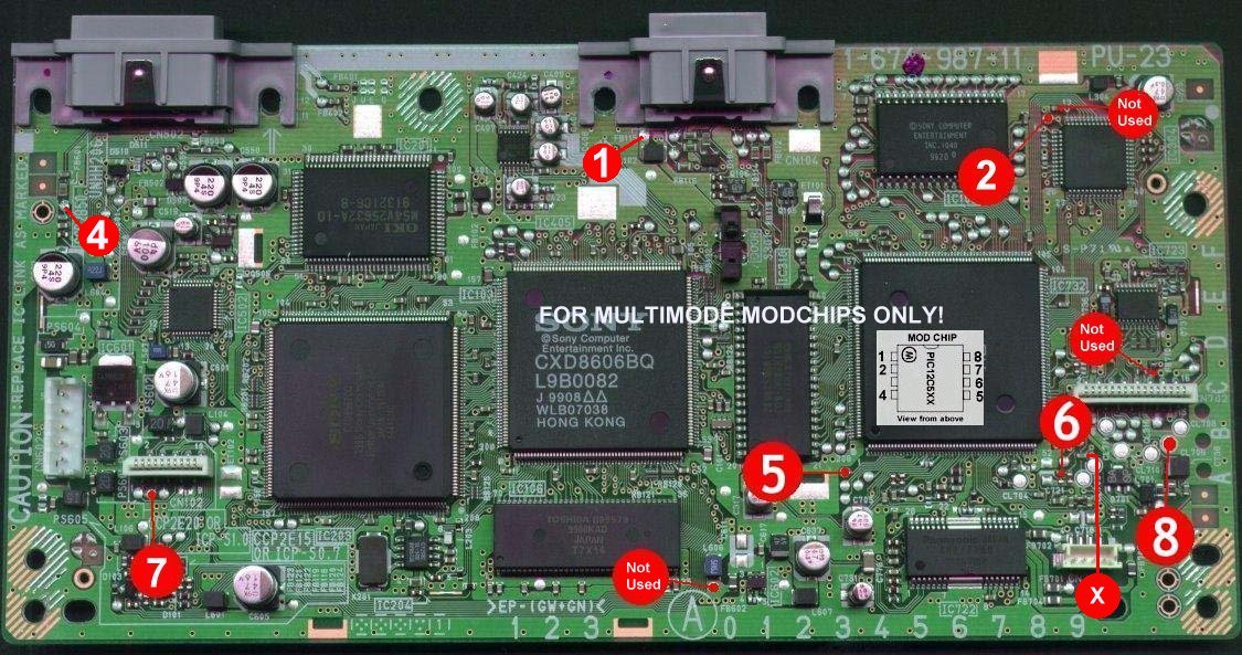
NOTE:
Pin 7 of MULTIMODE 1.5 Modchip connects to the memory card/joypad connector.
NOTE: With MULTIMODE 1.5 you don't need to connect two wires from
PIN 5 or solder a link wire.
Just connect the chip as shown in the diagram with one wire coming from PIN5. If for any
reason this method does not work on your machine then revert back to the old method and
connect a link wire from the point marked "5" to the
point marked "X"
Solder to the locations indicated below :-
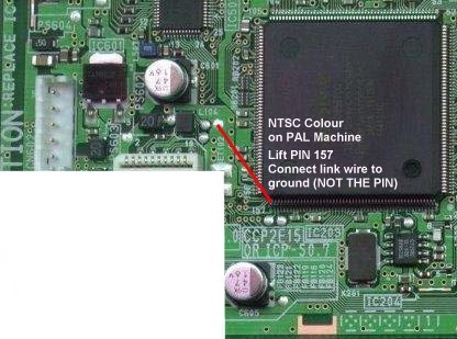
Additional:
If you are an expert you may like to try and also do a
colour correction modification.
This involves lifting PIN 157 and connecting the link wire to where PIN 157 once
connected.
This little mod enables you to play your imported games in colour without using a scart
lead.
I recommend that only an expert attempts this particular type of modification.
The diagram below shows you how to colour mod your PU23 board.